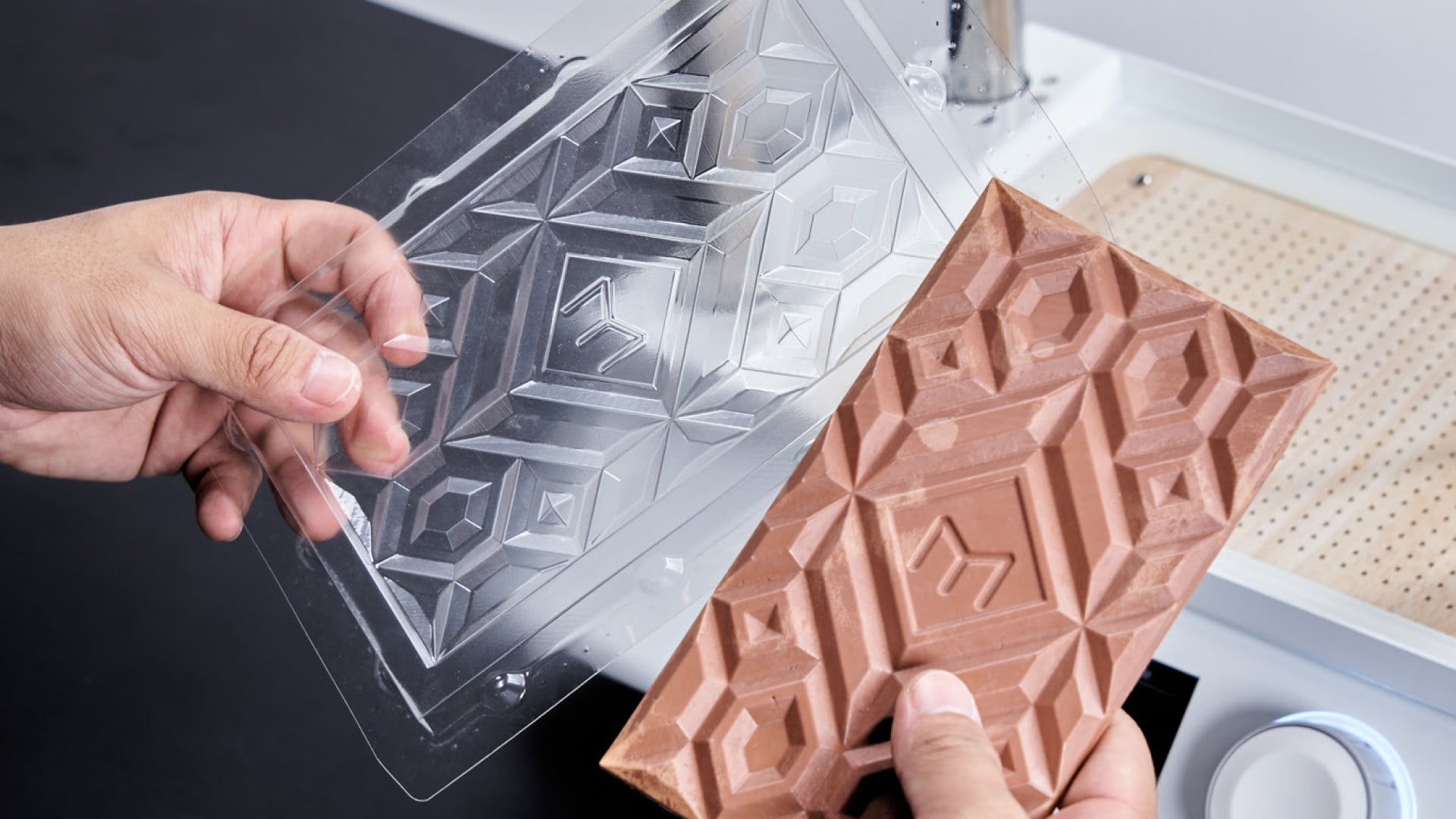
Vacuum forming is a popular manufacturing process that involves heating a plastic sheet until it becomes flexible, then shaping it over a mould using vacuum pressure. Once the plastic cools and hardens, it retains the shape of the mould, creating a durable and functional part.
This process is widely used in industries such as packaging, automotive, medical devices, and consumer goods because it allows for the production of detailed, high-quality parts with relatively low tooling costs. Vacuum forming is ideal for both prototyping and large-scale manufacturing, but to achieve the best results, careful design considerations are essential to ensure the final product is strong, precise, and visually appealing.
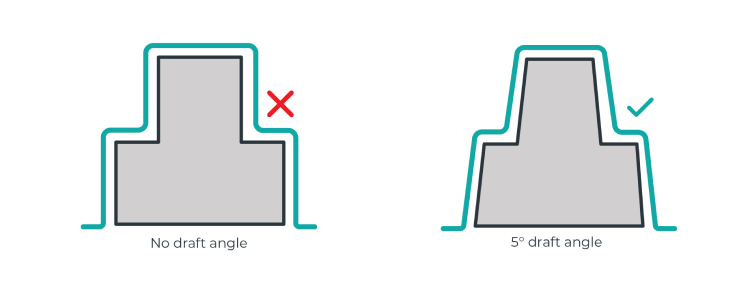
Use draft angles for easy mould release
Draft angles are an essential part of thermoforming design. These are subtle slants added to vertical walls to make it easier for the formed part to be removed from the mould. Without a draft angle, the plastic could get stuck, making demoulding difficult or even damaging the part.
Manufacturing templates with draft angles is well-suited to technologies like 3D printing or CNC milling. However, when using methods such as laser cutting, traditional draft angles cannot be produced. In these instances, you can design the template with an inclined plane divided into several small steps instead of one continuous vertical wall.
Best practices
- It is recommended to use a draft angle between 3-5 degrees to ensure a smooth release.
- For deeper or more complex moulds, a larger draft angle may be necessary.
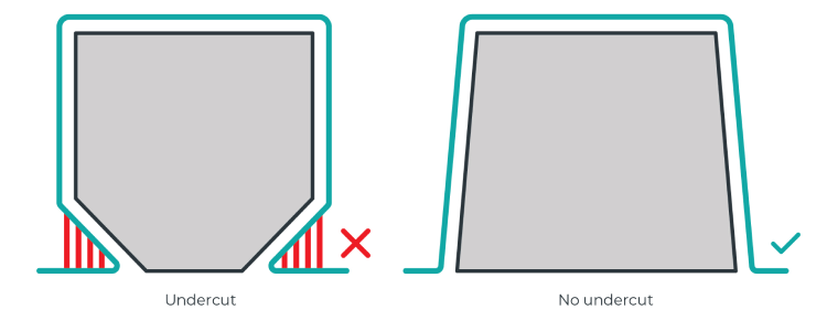
Minimise undercuts
Undercuts are features that prevent a part from being easily removed from the mould. It can complicate the forming process and may require multi-part moulds or additional tooling.
Best practices
- Minimise or eliminate undercuts for simpler and more cost-effective moulds.
- If your design requires undercuts, consider creating a template consisting of multiple slotting parts to help release the formed part.
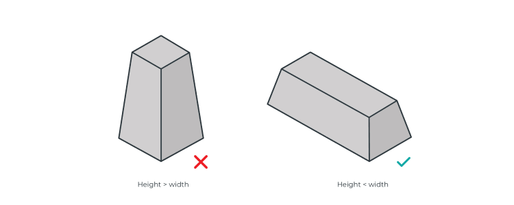
Width-to-height ratio (draw ratio)
In the vacuum forming process, the height-to-width ratio (also known as the draw ratio or forming depth ratio) needs to be properly controlled to ensure forming quality, prevent material tearing or deformation, and facilitate easy demoulding.
Best practices
- The height should not exceed 2 to 3 times the width to prevent excessive thinning or tearing.
- Shallow moulds (low height):
- Best for thicker or rigid materials with minimal deformation.
- Suitable for applications like trays, signs, and similar products.
- Deep moulds (taller height):
- Require thinner, more stretchable materials to avoid excessive thinning.
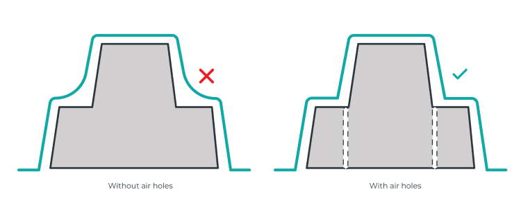
Optimise airflow with air holes
Proper airflow through a forming template plays a crucial role in achieving high-quality, detailed parts. By strategically adding air holes, you can enhance mould accuracy, prevent air pockets, and ensure even plastic distribution during the forming process.
Why do air holes matter?
During vacuum forming, air can become trapped in cavities or sharp corners of the mould, creating bubbles, distortions, or incomplete formations. Incorporating air holes helps evacuate trapped air, allowing the plastic sheet to form smoothly against the mould, capturing fine details with precision.
Best practices
- Target cavities and sharp features. If your template has deep recesses, sharp steps, or intricate details, place air holes near edges and corners to guide plastic flow effectively.
- Use small, discreet holes. Air holes should be small enough to remain inconspicuous on the final part but effective in releasing trapped air. A diameter of 0.5 mm is typically ideal.
- Space them sparingly. Overuse of air holes can weaken the mould or cause unwanted marks on the final product. Instead, focus on strategic placement near problem areas.
Recommended air hole sizes for different manufacturing methods
| Manufacturing method |
Recommended air hole size & shape |
| SLA 3D printing |
0.5 mm diameter tapered air hole |
| FDM 3D printing |
Minimum 0.5 mm diameter, larger if needed for printer resolution |
| SLS 3D printing |
No air holes needed (material is naturally porous) |
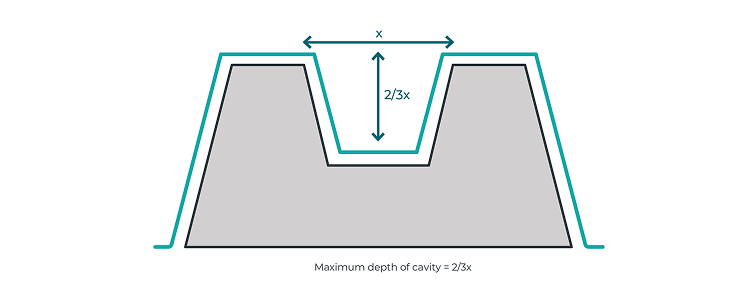
Cavity depth in your forming template
When a plastic sheet is moulded into a 3D shape, its surface area expands, and its thickness decreases. However, different templates cause varying levels of sheet thinning. For instance, if a template doubles the surface area of the plastic sheet, its average thickness will reduce by half. It's also important to note that the thickness is rarely uniform across the entire part, meaning some areas may end up thicker than others.
The sheet thinning ratio becomes particularly important when the template has a cavity. In such cases, the depth of the cavity should not exceed two-thirds of the width of its surface opening. Exceeding this ratio increases the risk of producing a part with overly thin surfaces, which can compromise its quality.
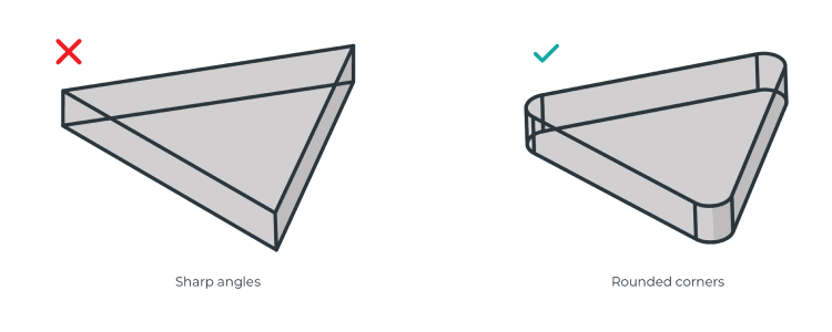
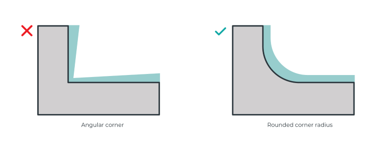
Avoid sharp angles
Vacuum forming is not always ideal for templates with sharp angles, particularly those smaller than 90°. Sharp vertical corners, combined with limited draft angles, make it more likely for the plastic sheet to tear or web during the forming process. To prevent this and enhance the quality of the part, ensure that all corners and edges of the template are rounded.
Best practices
- Sharp edges can cause excessive stretching and stress concentration, leading to tearing.
- Recommended corner radius (R) of at least 3–5 mm, depending on the material.
Corner radius and material flow
During vacuum forming, the heated sheet material gradually conforms to the template, eventually cooling and solidifying in place. As the material approaches corners, it tends to thin out.
To maintain consistent thickness and improve the part's structural integrity, it’s important to round off the corners and edges. A rounded corner radius ensures a smooth flow of material, reducing the risk of weak or inconsistent areas in the final part.
The template's surface texture
Thermoformed parts can replicate the surface texture of the template, even if the texture is not immediately visible. This is an important consideration during the design phase. If you're aiming for a smooth surface, you may need to perform post-processing on your template to achieve the desired finish.
The amount of post-processing required will depend on the template manufacturing technology used. For instance, FDM (Fused Deposition Modeling) 3D printing typically results in more noticeable layer lines compared to templates created using SLA (Stereolithography) 3D printing.
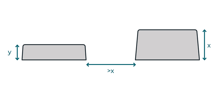
Template placement and preventing webbing
When placing multiple templates or design features close together, webbing may occur during the vacuum forming process. To avoid this, it's important to leave a gap larger than the height of the tallest feature in your template.
This guideline is especially critical for male moulds, where webbing can negatively impact the final part. However, in female templates, webbing has a lesser impact since it occurs on the inside, which doesn’t affect the final part.
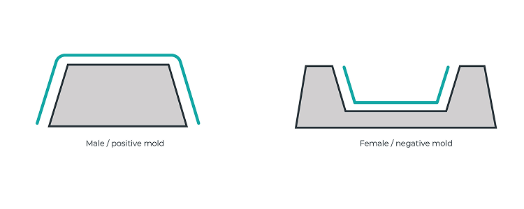
Male vs female templates
Pressure forming uses male or female templates depending on the type of part being produced. The side of the material that contacts the tool-face is the most dimensionally consistent, so it's important to define the part based on the side of the material that will touch the template.
- Male templates feature positive or convex shapes.
- Female templates have negative or concave shapes.
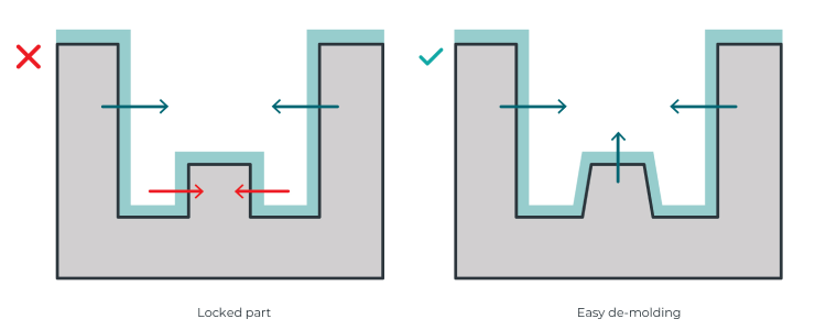
Design for shrinkage
During the cooling process, edges may release, but internal parts can become trapped. To prevent this, add draft angles to any design features that are at risk of being locked during cooling.
The diagram below illustrates the direction of shrinkage during cooling: areas in green will release, while those in red are at risk of being locked in place.
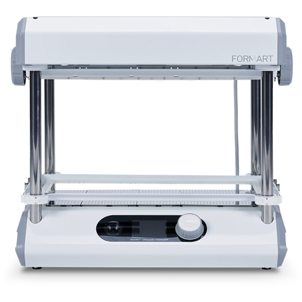
Choosing the right vacuum former for your project
Now that you understand how to design good moulds, selecting the right vacuum forming machine is the next step to achieving high-quality results.
MY YARD offers complete, all-in-one desktop vacuum formers, suitable for both beginners and professionals. Every MY YARD vacuum forming machine comes with a built-in vacuum pump, eliminating the need for an external pump or vacuum cleaner. Thanks to their high-quality heating elements, MY YARD vacuum formers heat material sheets quickly and evenly.
Whether you are new to vacuum forming or still learning, MY YARD vacuum forming machines will make your experience easier with their user-friendly interface and built-in materials database. You will always find the right forming settings for every project.
This article was originally posted on myyardtech.eu.